
Now we’re finally ready to solder new motor leads on. Again, please ensure that your motor is oriented exactly as in the photo below, to ensure my explanations of “top/bottom” are correct:
 |
| Motor oriented with field core at left, bobbin winding assembly at top right. |
In Part 13 we cut the old motor leads, leaving the top one an inch long, the bottom an inch-and-a-half long, as shown here:
 |
| The top lead is 1" long here. |
This is the maximum length we can leave them and still fit everything inside; we’ve cut them to this length to give you first-timers an opportunity to braid the new wire on without the leads being impossibly short.
However, the ideal length is really about 3/4" or less for the top motor lead, and 1.25” for the bottom motor lead. Here’s a photo of a different motor to which I’ve cut the top lead quite short:
 |
| The top lead is 3/4" long here. Harder to do, but better. |
Braiding a new wire to a connection that short can be challenging, particularly when you cannot quite get your fingers around the shorter lead coming out of the winding. It requires a fair amount of practice. If you feel you’re up to it, go ahead and cut the leads to this ideal length, but be aware there’s no going back.
In any case, get those leads as close to the ideal as you’re comfortable with, then let’s get started.
Cut two 8-inch pieces of new 18 AWG wiring. (Use different colors, obviously. I prefer red and black because those correspond with the colors on the terminal body where they will attach.) Strip the ends to a 1/2-inch or 3/4-inch, depending on what you became comfortable braiding during your soldering practice.

Don’t forget to individually braid the ends.

Then, braid the BLACK wire to the BOTTOM motor lead, and the red wire to the top lead.

Set up your Helping Hands, placing at least one of the alligator clips between your joint and the winding. This is so the clip will act as a “heat sink,” absorbing the heat from the soldering iron instead of letting it flow into the winding. Be mindful that the clip may get quite hot, so don’t forget to let it cool before you touch it.

Then, solder away, as we practiced in Part 3.
Next, cut some of the 1/8” heat shrink tubing to whatever length will cover all of the exposed wiring, going right up to the winding. Be sure to cut the heat shrink tubing so that just 1/8” of it will overlap with the existing insulation on the new motor leads. (Don’t make it overlap any further than that, or it will give us trouble later.) Then slide the heat shrink tubing onto each motor lead from the tail end.

You may remember that I left some of the old insulation on near the base of the bottom motor lead. Here you can see that, in addition to covering the new joint with the 1/8” stuff, I’ve covered the thicker leftover insulation with the 3/16” heat shrink tubing, as the 1/8” would not fit over that section.

In the photo above, you also see that I’ve stacked the motor even higher up with more blocks, so I could comfortably fit a lighter beneath it. It may look precarious, but rest assured I’ve checked it for stability, so the whole thing doesn’t come tumbling down as I’m working on it.
Once I’ve finished the heat-shrinking, I take the motor off of the blocks for the next step.

Now we tie the underwriter’s knot that we practiced earlier.

Since we practiced “moving” the knot down the wiring before, you should have no problem getting the knot exactly where you want it. And where you want it is right up to the heat-shrink tubing.
Heat-shrink tubing is stiff and doesn’t bend well, by the way, which is why we made sure it didn’t overlap too much with the insulation on the new wiring. If we made that mistake, that would move our knot further out than we want it, which might prevent us from closing the motor.
Get the knot as tight as you can get it, but be careful that you don’t place a lot of stress on the motor leads where they go into the winding. That is the most vulnerable part of this operation.

Next, take some of the larger, 3/16” heat shrink tubing and cut a piece exactly 3 inches long.

Use it to cover both leads...

...sliding it all the way down to the knot.

Then heat-shrink it with your lighter.
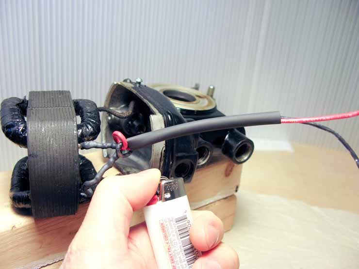
Now it's heat-shrunk. Don't worry if the tails of the wiring are going all over the place, we'll sort that out later.

Finally, route the wires from the inside of the motor out through the grommet. With my left hand I keep my fingers on the base of the motor leads, to prevent stressing their connection to the windings, while I use my right hand to thread the wires out through the grommet hole. (My right hand is absent in the photo because it's holding the camera.)

Now we're in good shape. But don't connect the field core to the motor housing just yet, there's a trick to it we've got to cover.
Go on to Part 16: Re-attaching the Field Core
VERY NICE.
ReplyDeleteThe next step #16 doesn't work. I will replacing the motor wires on a 201 in the next few days.. Is there something important I should know about reattaching the field core? Thank you! This blog series has been in valuable to me!
ReplyDelete"The next step #16 doesn't work."
DeleteThe link has been fixed! Thank you for bringing it to my attention.